
Compression limiters and captive bolt assemblies are engineered solutions to protect plastic or soft substrates from damaging compressive loads when bolts clamp components together. Instead of the bolt head or washer pressing directly against the plastic, which can crush, deform, or crack it, a compression limiter takes that force. Captive bolt assemblies integrate both the limiter and the bolt into one unit, simplifying handling and improving reliability.
PRODUCT INDEX
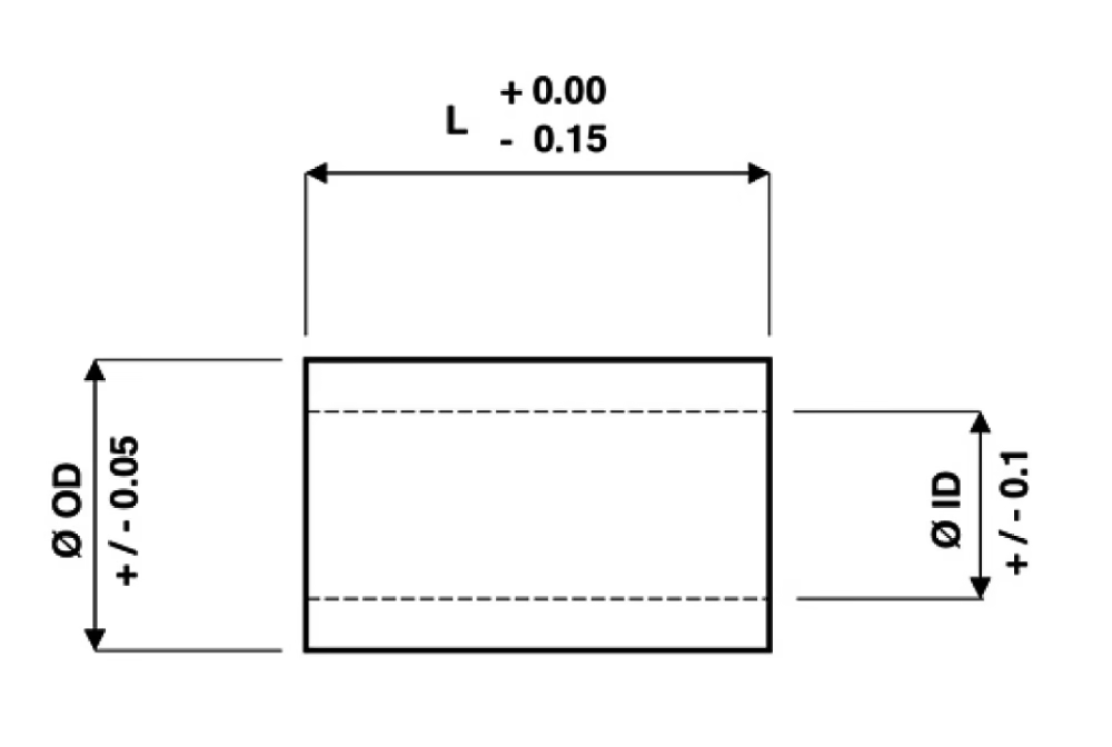
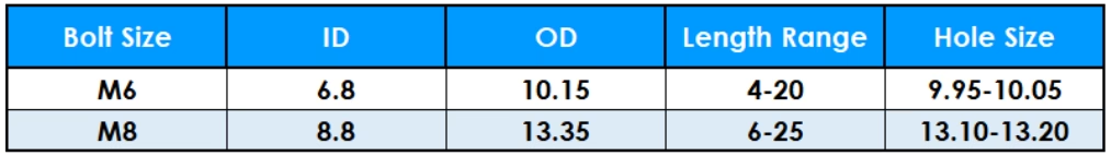
SOLID
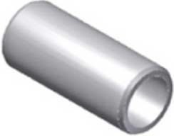
Solid compression limiters have a plain round inside and outside diameter and they are installed using a simple cold press method of installation. They offer high compressive strength, available in standard, high strength and custom ranges. Commonly made in steel by cold forming, brass and aluminium also available often made by machining.
HEADED
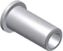
Headed compression limiters offer the benefits of the Solid tube, plus the addition of a head. The head can be placed at the mating face of soft materials like aluminium, to spread the induced load over a greater area, thus reducing the stress. The head can also be placed at the bolt face, if a greater contact area with the plastic is required.
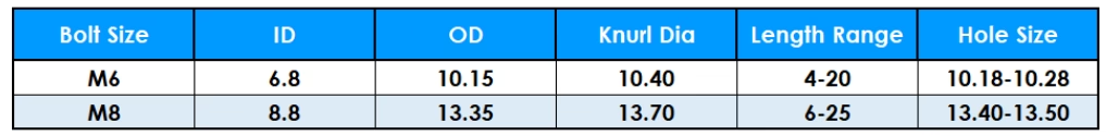
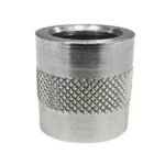
KNURLED
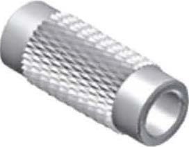
Knurled designs provide additional push-out resistance, often a requirement with short compression limiters. Complex knurled designs are available where designers want the compression limiter to be longer than the plastic thickness, thus totally isolating the plastic from the bolted joint.
OVAL

With some components, designers use an oval hole to datum their component to it’s mating threaded component in one plane, whilst allowing radial clearance in the other.
SPLIT
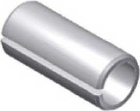
Split compression limiters are produced from rolled strip, this process can offer cost benefits. However, they are generally used on less demanding application where tolerance, form, flatness and roundness are not so critical.
CLA
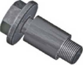
Compression Limiter Assemblies (CLA) combine the compression limiter and its mating bolt, they provide the necessary axial and radial float during bolt assembly. They eliminate bolt handling at the assembly stage and also provide logistical and procurement cost savings.
CORE PRINCIPLES
- A compression limiter is a sleeve or tube placed between the bolt head (or mating component) and the plastic surface. It absorbs compressive loads, transferring minimal stress to the plastic.
- The limiter usually contacts only a portion of the plastic surface or sits in a recess or boss, reducing peak stresses.
- Captive bolt assemblies (CLAs) combine the limiter and fastener into one piece, often with axial float or radial freedom to ease alignment.
- They maintain a defined clearance or “floating” behavior during assembly, preventing handling issues and misalignment.
DESIGN GUIDE
HOLE DESIGN
Compression limiters can generally be installed into a standard 1.0° inclusive moulded hole. However, the length of the compression limiter, required retention, maximum insertion force, and boss wall thickness should be considered when selecting the hole diameter. The hole taper should always produce a larger hole at the insertion side, to aide location and installation. In some instances a location counterbore is recommended particularly with Split types. For long compression limiters an interference fit may only be required over a reduced section of the compression limiter.
COMPRESSION LIMITER LENGTH
The common method used to determine the compression limiter length relationship to the plastic is the minimum plastic thickness, equals the maximum compression limiter length. With this method the force transferred to the plastic is minimised, at the same time it ensures the plastic component is securely clamped and prevented from moving.
PLASTIC BOSS WALL THICKNESS
The plastic boss wall thickness is very much dependant on the application requirements and moulding design. The amount of stress / force transferred to the boss during installation and bolt assembly should always be considered. Based on typical applications we suggest a minimum wall thickness equal to 50% of the bolt diameter, this would equate to 3.0mm for a M6 compression limiter.
CUSTOM DESIGNS
Headed, Oval, Split and Compression Limiter Assemblies are “Custom Designs”, the form and sizes have to be specified to suit the particular application. Please contact PSM or your local representative – we would be pleased to review your application and propose the most cost-effective solution.
ADVANTAGES & USE CASES
- They protect plastic parts from compressive damage during assembly, extending part life.
- Captive assemblies reduce handling steps and ensure correct orientation and alignment upon assembly.
- Common in consumer electronics, automotive plastic assemblies, lighting housings, instrument panels, or any design where plastic parts are clamped.
- They decouple compressive forces, hence they offer design freedom. This allows thinner plastics or less robust bosses where otherwise impossible.
Best Practices & Recommendations
- Prototype to validate stresses and ensure the limiter protects the plastic under load.
- Choose variant (solid, headed, knurled, split) based on local geometry and retention needs.
- Control interference fits and avoid overhanging lengths that press plastic.
- Design bosses with adequate thickness and support ribs to resist compressive stress.
- For captive bolt assemblies, maintain the intended floating clearance so alignment tolerance is preserved.
- Consult manufacturer input for nonstandard materials or finishes to match environmental, strength or corrosion requirements.
STANDARD RANGES
Standard Material – Steel (S)
Standard Finish – Trivalent Zinc + Sealer (W)
Special Materials – Brass (B), Aluminium (A)
Other finishes available on request
STANDARD – SCL200-SERIES

HIGH STRENGTH – HCL350-SERIES
HIGH STRENGTH – HCL350-SERIES
HOW TO SPECIFY
Enhance Your Assembly with Our Precision Compression Limiters & Captive Bolt Assemblies
Start browsing our products or request a quote today to find the ideal fastening solution for your application.