

Other materials and lenghts possible on quotation.

$0.43
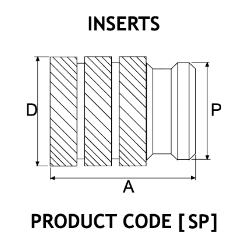
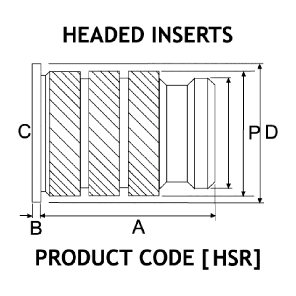
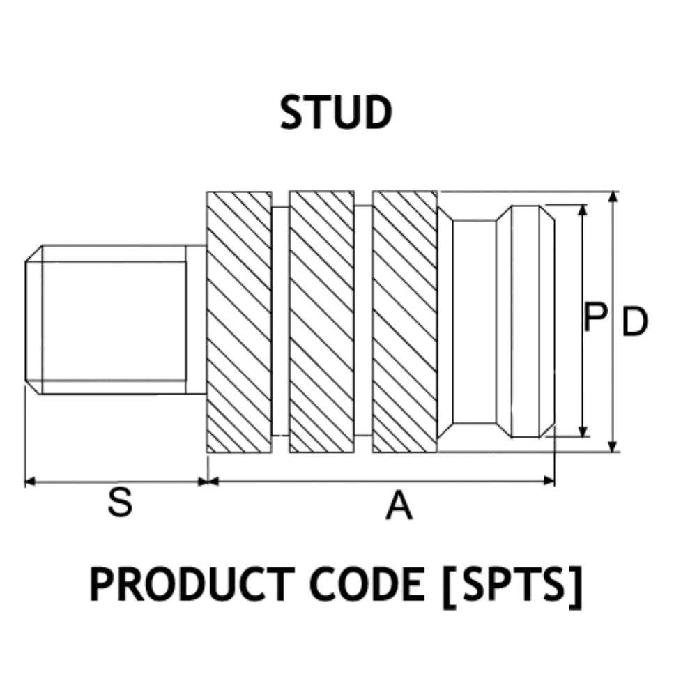
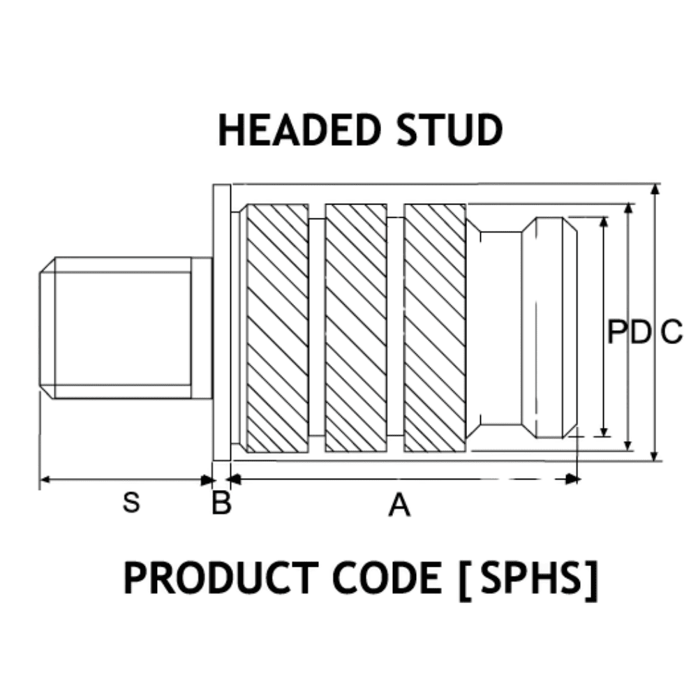
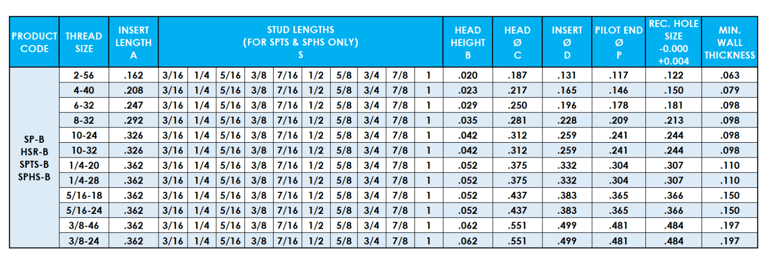
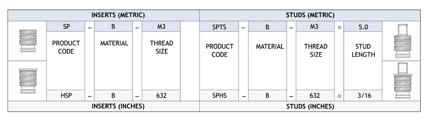
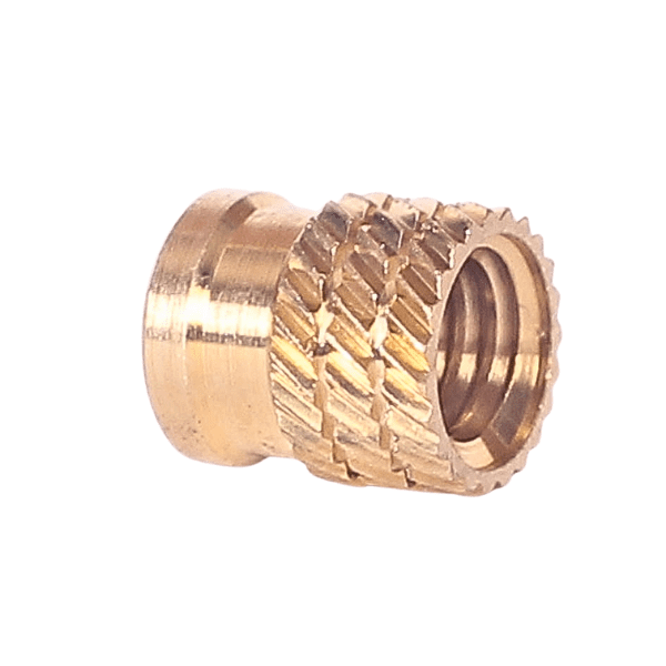
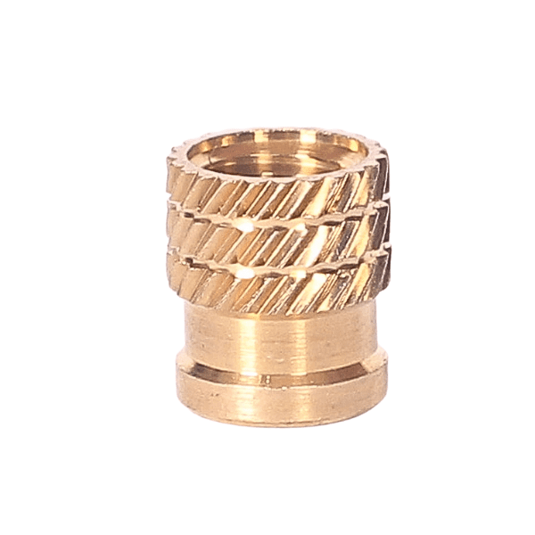
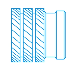
Insert Type SP & HSR series and Stud Type SPTS & SPHS series – Designed to cope with the difficulties presented by hard brittle thermoset materials. The sharp precision knurl pattern cuts into these materials reducing radial stresses and allowing thinner boss walls than many other inserts.
| Weight | 0.001543 kg |
|---|---|
| Dimensions | 1 × 1 × 1 cm |
| Product Type 1 | |
| Product Type 2 | |
| Material | |
| Thread | |
| Size | |
| Length/Dimension | |
| Special Notes | |
| Bin Location | |
| Default Location | |
| Lead Time |
There are no reviews yet.