
Fast Global Shipping
Bulk Discounts
Over 10,000+ Product Variations
Trusted by 100,000+ Customers
Fin-Lok
Advantages
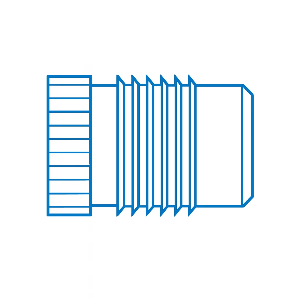
PSM Fin Lok® inserts are press-in inserts designed for use in thermoplastic materials. They deliver a durable, reusable threaded interface without requiring tapping operations. The combination of sharp fins and straight knurls allows easy insertion and strong retention in plastic substrates. Unlike many inserts, Fin-Lok offers a free-running thread, simplifying screw insertion and removal.
- Easy press-in insertion
- High pull-out performance in most thermoplastics
- Self-aligning - assists installation
Key Features
- Press-in insertion, installed by squeeze press action without special tooling
- Sharp fins and straight knurls provide high pull-out strength while minimizing radial stress
- Self-alignment ensures the insert settles squarely during installation
- Free-running thread allows easy screw engagement without cutting or deformation
- Available in flanged and stud versions for different mounting needs
Selection of Inserts
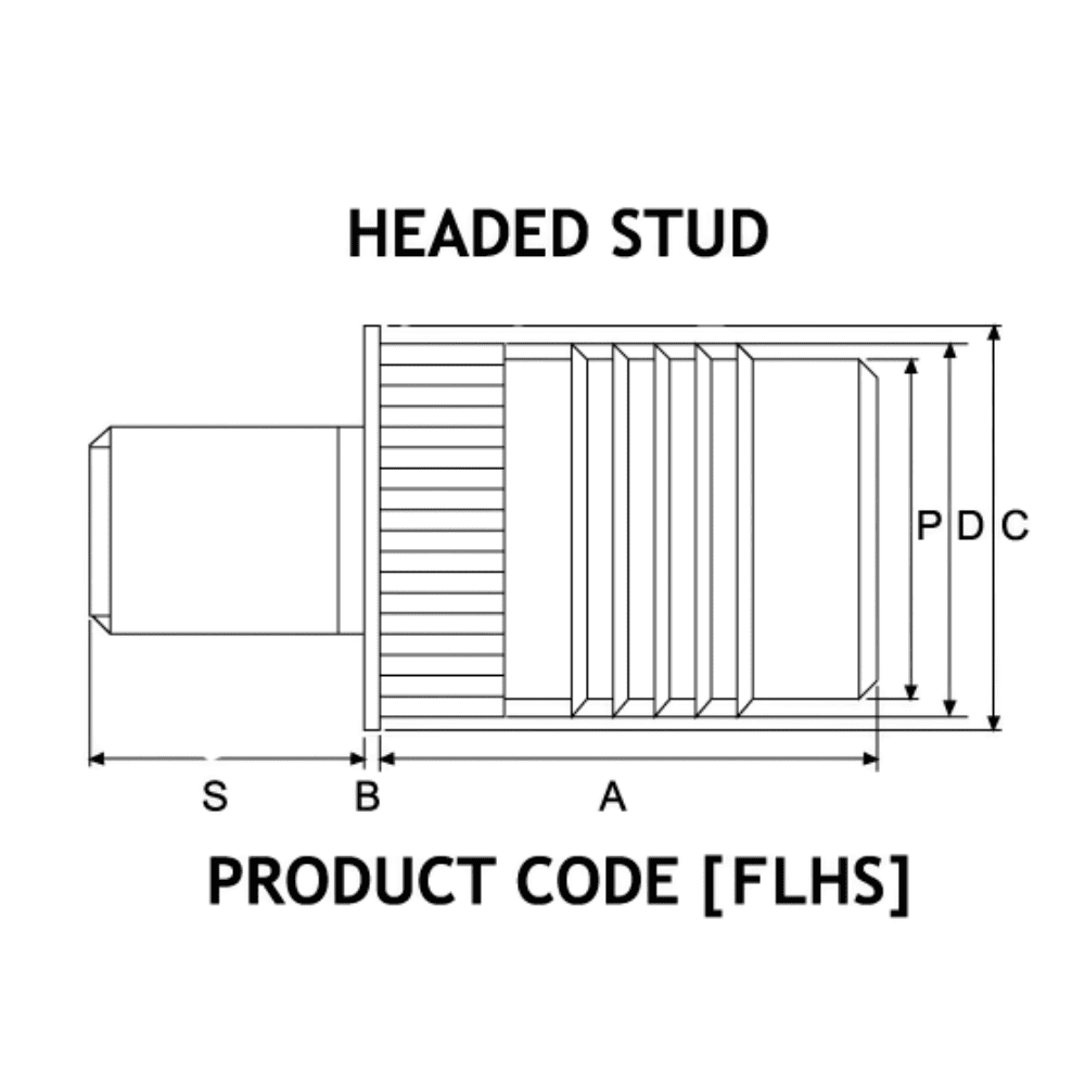
ISO Metric
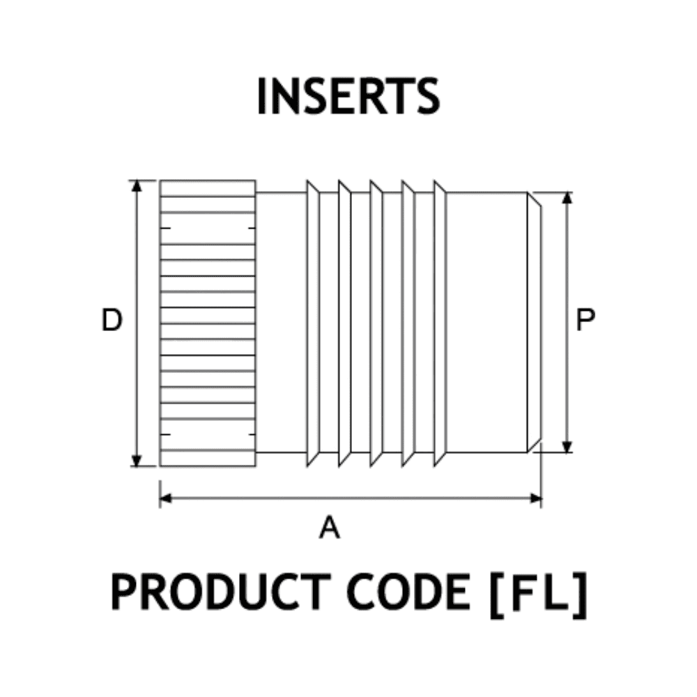
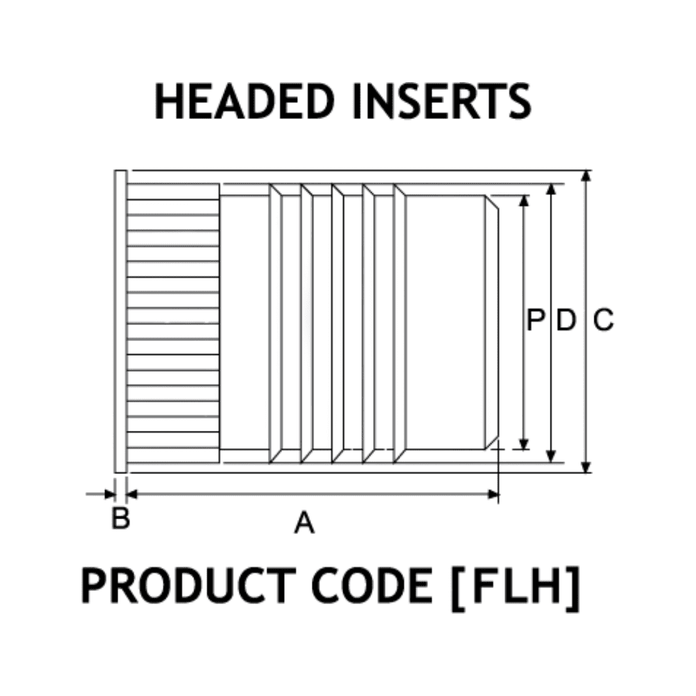
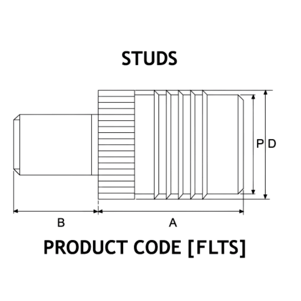
| PRODUCT CODE | THREAD SIZE | INSERT LENGTH A | STUD LENGTHS (FOR FLTS & FLHS ONLY) S | HEAD HEIGHT B | HEAD ø C | INSERT ø D | PILOT END ø P | NO. OF FINS | REC. HOLE SIZE -0.00 +0.10 | MIN. WALL THICKNESS | |||||||||
|---|---|---|---|---|---|---|---|---|---|---|---|---|---|---|---|---|---|---|---|
|
FL-B FLH-B FLTS-B FLHS-B | M2 | 4.0 | 5 | 6 | 8 | 10 | 12 | 14 | 16 | 18 | 20 | 25 | 0.45 | 4.8 | 3.7 | 3.1 | 2 | 3.2 | 1.6 |
| M2.5 | 4.8 | 5 | 6 | 8 | 10 | 12 | 14 | 16 | 18 | 20 | 25 | 0.58 | 5.5 | 4.5 | 3.9 | 3 | 4.0 | 2.0 | |
| M3 | 4.8 | 5 | 6 | 8 | 10 | 12 | 14 | 16 | 18 | 20 | 25 | 0.58 | 5.5 | 4.5 | 3.9 | 3 | 4.0 | 2.0 | |
| M3.5 | 6.4 | 5 | 6 | 8 | 10 | 12 | 14 | 16 | 18 | 20 | 25 | 0.74 | 6.4 | 5.3 | 4.7 | 4 | 4.8 | 2.4 | |
| M4 | 7.9 | 5 | 6 | 8 | 10 | 12 | 14 | 16 | 18 | 20 | 25 | 0.89 | 7.1 | 6.1 | 5.5 | 5 | 5.6 | 2.8 | |
| M5 | 9.5 | 5 | 6 | 8 | 10 | 12 | 14 | 16 | 18 | 20 | 25 | 1.07 | 7.9 | 7.0 | 6.3 | 5 | 6.4 | 3.2 | |
| M6 | 12.7 | 5 | 6 | 8 | 10 | 12 | 14 | 16 | 18 | 20 | 25 | 1.32 | 9.5 | 8.6 | 7.9 | 7 | 8.0 | 4.0 | |
| M8 | 12.7 | 5 | 6 | 8 | 10 | 12 | 14 | 16 | 18 | 20 | 25 | 1.32 | 11.1 | 10.2 | 9.5 | 7 | 9.6 | 4.8 | |
Other lengths possible on quotation.
Unified
| PRODUCT CODE | THREAD SIZE | INSERT LENGTH A | STUD LENGTHS (FOR FLTS & FLHS ONLY) S | HEAD HEIGHT B | HEAD ø C | INSERT ø D | PILOT END ø P | NO. OF FINS | REC. HOLE SIZE -0.000 +0.004 | MIN. WALL THICKNESS | |||||||||
|---|---|---|---|---|---|---|---|---|---|---|---|---|---|---|---|---|---|---|---|
|
FL-B FLH-B FLTS-B FLHS-B | 2-56 | .157 | 3/16 | 1/4 | 5/16 | 3/8 | 7/16 | 1/2 | 5/8 | 3/4 | 7/8 | 1 | .018 | .189 | .147 | .123 | 2 | .126 | .063 |
| 4-40 | .187 | 3/16 | 1/4 | 5/16 | 3/8 | 7/16 | 1/2 | 5/8 | 3/4 | 7/8 | 1 | .023 | .217 | .178 | .154 | 3 | .157 | .079 | |
| 6-32 | .250 | 3/16 | 1/4 | 5/16 | 3/8 | 7/16 | 1/2 | 5/8 | 3/4 | 7/8 | 1 | .029 | .250 | .209 | .185 | 4 | .189 | .094 | |
| 8-32 | .312 | 3/16 | 1/4 | 5/16 | 3/8 | 7/16 | 1/2 | 5/8 | 3/4 | 7/8 | 1 | .035 | .281 | .240 | .218 | 5 | .220 | .110 | |
| 10-24 | .375 | 3/16 | 1/4 | 5/16 | 3/8 | 7/16 | 1/2 | 5/8 | 3/4 | 7/8 | 1 | .042 | .312 | .274 | .248 | 5 | .252 | .126 | |
| 10-32 | .375 | 3/16 | 1/4 | 5/16 | 3/8 | 7/16 | 1/2 | 5/8 | 3/4 | 7/8 | 1 | .042 | .312 | .274 | .248 | 5 | .252 | .128 | |
| 1/4-20 | .500 | 3/16 | 1/4 | 5/16 | 3/8 | 7/16 | 1/2 | 5/8 | 3/4 | 7/8 | 1 | .052 | .375 | .337 | .310 | 7 | .315 | .157 | |
| 1/4-28 | .500 | 3/16 | 1/4 | 5/16 | 3/8 | 7/16 | 1/2 | 5/8 | 3/4 | 7/8 | 1 | .052 | .375 | .337 | .310 | 7 | .315 | .157 | |
| 5/16-18 | .500 | 3/16 | 1/4 | 5/16 | 3/8 | 7/16 | 1/2 | 5/8 | 3/4 | 7/8 | 1 | .052 | .433 | .400 | .375 | 7 | .378 | .189 | |
| 5/16-24 | .500 | 3/16 | 1/4 | 5/16 | 3/8 | 7/16 | 1/2 | 5/8 | 3/4 | 7/8 | 1 | .052 | .433 | .400 | .375 | 7 | .378 | .189 | |
Other materials and lengths possible on quotation.
Specifying an Insert & Stud
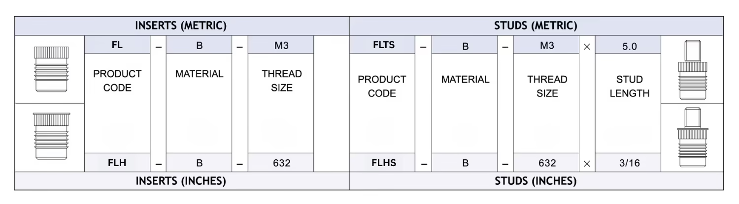
Boss Design Specification
Hole Preparation
Molded holes are recommended wherever possible. The taper on a molded hole should be 1° inclusive and the hole diameter recommended should apply at the point reached by the bottom of the insert. The top of the hole should not be chamfered or counterbored and care must be taken to avoid bell mouthing. Hole diameter tolerance: -0.00 +0.10mm.
Installation
The inserts must be installed using a steady squeeze action press. A hammer blow type installation will prevent plastic flow and may damage the boss.
Wall Thickness
A general guide to minimum wall thickness is given in the data table but this will vary depending upon the nature of the plastic. Where thinner walls are required these can often be accommodated, but consultation with the P.S.M Technology Centre or local sales office and pre-production testing is strongly advised.
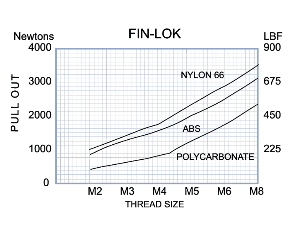
Performance Data
The complexity of materials and variations in service conditions make it impossible to detail fastener performance for specific applications. The chart below gives a general guide and show the relative performance of the inserts in the range.
Enhance Your Assembly with Our Precision Fin-Lok Inserts
Start browsing our products or request a quote today to find the ideal fastening solution for your application.
Frequently Asked Questions About Fin-Lok Inserts
What are Fin-Lok Inserts and what are they used for?
Fin-Lok inserts (series FL, FLH, FLTS, FLHS) are press-in brass threaded inserts designed for installation into most thermoplastic materials. They are used to create strong, durable, reusable internal threads in plastic components — such as moulded housings, enclosures, and structural plastic parts — where a reliable threaded fixing point is required without welding, tapping, or heat equipment. Fin-Lok inserts are manufactured by PSM International and are part of the broader Inserts for Plastics range.
What is the difference between FL and FLH Fin-Lok Inserts?
What are FLTS and FLHS Fin-Lok Stud Inserts?
FLTS and FLHS are stud variants within the Fin-Lok family. Rather than providing an internal threaded hole for a screw, these types feature an external threaded stud protruding from the insert body once installed. FLTS is the standard stud version, while FLHS is the headed stud version (with a flange). They are used where a permanently fixed, protruding threaded stud in a plastic component is required — for example, to mount panels, brackets, or components onto a plastic housing using a nut from the outside.